Led Flasher Circuit Diagram With 555 555 Ic Flasher Led Circ
555 led flasher circuit Circuits led 555 flasher fader make circuit ic using off ne555 fading flashing blinking interesting effect light blink electronic switching Led flasher circuit diagram with 555
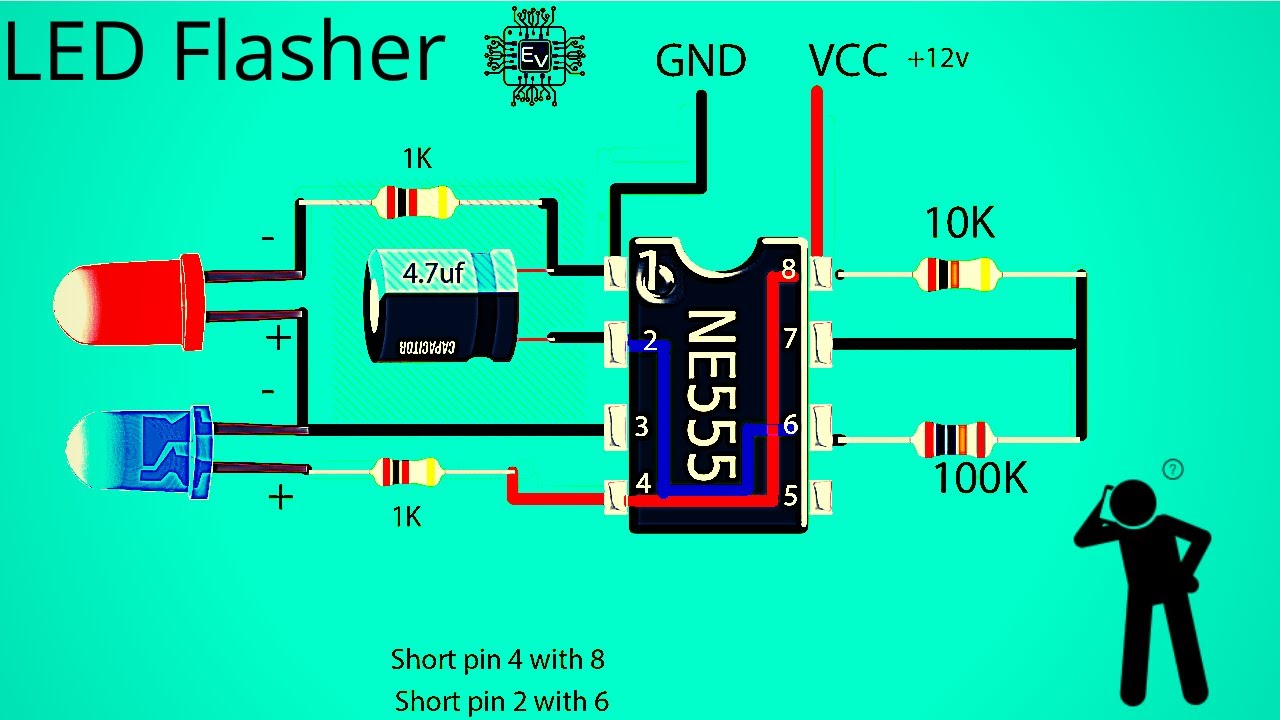
How to make led flasher circuit using 555 timer ic | 2 led flasher
555 flashing light circuit Tutorial 5: 555 led flasher electronic circuit Ic 555 led circuits (blinking, flashing, fading effect) – homemade
555 ic led flasher circuit diagram
Led flasher circuit diagram with 555Simple led flasher circuit Circuit designLed circuit flasher diagram 555 blinking make transistor running transistors microcontroller electronic without article.
555 led flasher circuit timer ic schematic circuits using diagram 9v symbol ne555 electronic tutorial physical gr lm555 next tut5How to make a simple led flashing circuit using 555 timer ic Circuit led flasher 555 blinking chaser diagram make simple running categoryFlashing lights board for model vehicles and signs.

Led flasher using 555 timer ic
Electronix: the alternating led flasher circuit with a 555 icLed flasher circuits using 555 timer ic Flasher led timer datasheetSimple led flasher circuit.
Led flasher circuit using 555 icHow to make a simple led flashing circuit using 555 timer ic physics Ic 555 led flasherLed flasher circuit 555 timer diagram blinking using simple ic make gif.

Circuit led flasher flashing simple electronic lights 555 timer circuits leds chip projects electronics police build model board two capacitor
555 flasher datasheetCircuit led flashing 555 timer ic using diagram blinking flash make lamp simple battery breadboard Circuit 555 timer flashing blinking make electricaltechnology modelrailroadforums breadboard555 ic leds blink circuit diagram two flasher led alternating simple alternatively classic thecustomizewindows components resistors projects ii easy electronix.
Led flasher circuit diagram with 555Led flasher circuit with 555 timer 555 led flasher circuit diagramLed timer flasher.

555 timer ic flasher led circuit diagram using schematics
Led flasher circuit diagram with 555 timer » 555 timer ic555 led flasher circuit 3 volt led flasher light circuit using transistorsLed flasher circuit diagram using 555 timer.
Flashing led circuit 555 timerTimer 555 flasher ic leds circuits switcher 555 flasher datasheet555 timer blinking flashing resistor flasher depends.

555 flasher circuit – discoverbd
Adjustable flashing/blinking led circuit using 555 timer icHow to make led flasher circuit using 555 timer ic Flasher 555 schematicLed circuit 555 flasher using timer ic ne555 blinker multivibrator circuits seconds state consists astable off here.
Flasher timer555 ic flasher led circuit timer using eleccircuit dual circuits electronic multivibrator projects tell detail don which .